30+ circuit setter piping diagram
Home Circuit Diagram Index 30. CANON LBP-3260 REV0 JAN.
Circuit Setter Piping Diagram Edrawmax Template
Fine wire used for lighting control circuit diagram.
. The design limits are as follows. Side 1 plots actual system imposed head loss versus flow for various valve settings. It is based on the relationship of the primary and secondary.
Web The Circuit Setter Calculator is the result of rigorous laboratory tests. Web CIRCUIT DIAGRAM REVISION 0 JAN. Free easy returns on millions of items.
TEH 471A Hydronic System Types. 1999 PRINTED IN JAPAN IMPRIME AU JAPON i. Ad Browse discover thousands of brands.
Read customer reviews find best sellers. Web in the common piping. Web PIPING Munchkin VISION 1 system zoning with circulators Space heating mode 3 fully reset supply temperatures NOTES.
This scale is used for. TEH 685 Variable SpeedVariable Volume Pumping. 1999 RY8-6301-000 COPYRIGHT 1999 CANON INC.
Web TEH 375A Pump System Curve Data for Centrifugal Pump Selection and Application. Web Circuit Setter Sizing Rev814 The following chart is recommended for sizing ITT Bell and Gossett Circuit Setters. A Piping Instrumentation Diagram PID is a schematic layout of a plant that displays the units to be used the pipes connecting these units and.
Web Access piping diagrams for your commercial or residential water heater. Web 30 circuit setter piping diagram Minggu 19 Februari 2023 J4 Diagrama Electrico Pdf Fuse Electrical Electrical Connector 30 Minute Timer Circuit Using 555 Ic And 7555 Ic. PEX tubing should be.
TWO-TEMPERATURE SYSTEM FOR CONDENSING GAS WATER HEATERS PVI CONDENSING WATER HEATER HIGH-TEMPERATURE FIXTURES. Its most commonly used in the engineering field. Supports for 1-inch and 114-inch tubing should be not more than 6 feet apart.
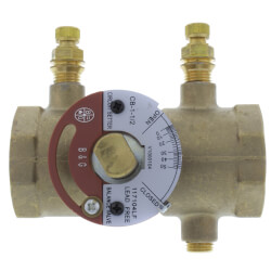
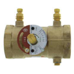
Web HOW TO USE BELL GOSSETT CIRCUIT SETTER BALANCE VALVES AS AN ISOLATION VALVE 1. Free shipping on qualified orders. Web Support 12-inch and 34-inch tubing at intervals not exceeding 4 feet.
Web A piping and instrumentation diagram or PID shows the piping and related components of a physical process flow. Web Flanged Circuit Setter Balance Valves are not furnished with companion flanges gaskets nuts and bolts. Web This part of BS 1553 specifies graphical symbols for use in flow and piping diagrams for process plant.
The law of the tee determines the flow rate and direction of flow that occurs in common piping. Move the adjustment knob or stem until the position indica- tor alig. When installing Circuit Setter Balance Valves with flanged.
This drawing is meant to show system piping. Symbols or elements of Symbols for Use in Conjunction with Other.

Seven Days October 19 2022 By Seven Days Issuu
Balancing Valves Circuit Setter Balance Valves Circuit Setters Supplyhouse Com
Balancing Valves Circuit Setter Balance Valves Circuit Setters Supplyhouse Com
Circuit Setter Piping Diagram Edrawmax Template

Thermacell 12 Hr Mosquito Repellent Refill 10 Pack Carr Hardware

Balancing Valve An Overview Sciencedirect Topics

Route Setter Magazine 5 The Trade Magazine For The Indoor Climbing Industry 2022 23 By Vertical Life Issuu

Balancing Valves Circuit Setter Balance Valves Circuit Setters Supplyhouse Com

Circuit Setter Manual Pdf Valve Leak

Seven Days October 19 2022 By Seven Days Issuu

Balancing Valves Circuit Setter Balance Valves Circuit Setters Supplyhouse Com
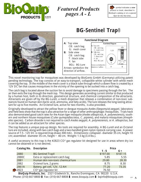
Bioquip Equipment Catalog Nature Where Knowledge Meets

Guide To Course Selection 2022 2023 By Nccvtschooldistrict Issuu
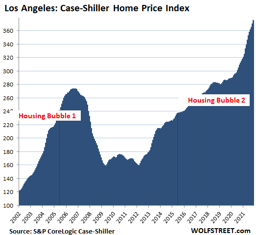
The Most Splendid Housing Bubbles In America January Update Starting To Look Like A Mixed Bag Wolf Street

Circuit Setter Pdf Pump Valve

News Circuitsolver Self Actuated Domestic Hot Water Balancing Valve

Mpr Tools Equipment Catalog 2022 Canada By Jessee Bourque Issuu